Phoenix II Features & Specifications

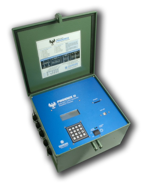
The Phoenix II is a stand alone unit that is designed to work with sensors to detect and classify vehicular traffic on interstates, highways and roads. smallphoenixiiformed.jpg

Robust military specification connectors provide easy wiring of sensors, inputs and outputs of the Phoenix II unit. The Phoenix II comes with a 4 line 20 character LCD display with a 16 alpha/numeric keypad. The Phoenix II has an internal 6 volt battery that is charged via the battery port by either AC or DC inputs for continuous uninterrupted operation.

Communications with the Phoenix II is provided by a RS232 serial connection or USB port allowing direct PC, standard data modem, cellular, and IP modems connectivity in real time. Extra high speed serial ports for vehicle output and local communications are optional.


*Optional functionality:  SD/MMC Flash Memory,  I-Loop, 900Mhz Wireless, USB, Secondary/Tertiary Serial ports, Optically isolated Loop outputs, Optically isolated alarm outputs, Remote sensor Inputs, Timed presence inputs, Incident detection.

Features

  •  Count 1-16 Lanes

Count methods include directional, lane subtraction, and normal.

  • Classify 1-8 lanes

Using any of three primary different data types the Phoenix II can record data for classification.  Class data can be collected in the following data storage types:

  • Binned – The most common data collected, binned allows for vehicles to be sorted into user defined bins of axles, speed, length headway and gap with a total of 30 bins per type depending on sensor configuration.
  • Per Vehicle Raw – Each vehicle record is stored with the following attributes:
    • Lane # - Time – Speed – Axles and Spacings – Overall Length
    • Time Stamped Sensor - This is the most basic of data types that will store sensor activations to allow for classification and sensor processing to be done post collection with PC software. While providing the most flexible data, sensor timestamp uses the most memory when collecting data.
  • Temperature an Battery Data Storage

When in collection mode the Phoenix II can be set to store temperature data and battery voltage data changes along with the count/class data in the counter files for later processing.

  • Independent Count

The Phoenix II unit includes an advanced feature for dual count and class operation to allow for count and class data to be collected simultaneously. This feature enables the unit to account for sites that may have some lanes that are functioning as classification and others that are not (ex: bad sensors eliminate the ability to classify vehicles in one or more lanes).

  • Record interval lengths from 1min to 24hr

The classifier can be programmed to use different interval lengths to record data. The following interval lengths are available:

1min, 2min, 5min, 10min, 15min, 30min, 1hr, 2hr, 4hr, 6hr, 12hr, 24hr(1day)

  • Onboard keyboard and LCD display

The 4 line 20 character per line LCD display allows real time vehicle data monitoring and programming of the unit via the 16 key alpha-numeric watertight keypad.

  • Dynamic Sensor assignment and calibration

Sensor assignment and calibration can be changed in the Phoenix II unit by the user on site or via telemetry to account for failing sensors or incorrect input of signals. This also allows for changing lane sensor configurations to accommodate sites with different lane setups.

  • Ultra Low power consumption with Smart Power Management

Designed for use in remote areas and urban sites alike, the Phoenix II can operate off very low power draw making it a viable solution for data collection with solar or ac/dc power source. The classifier also has smart power management to account for loss of power without losing data and providing auto reinitializing when power is restored to allow for the maximum up time in power event failures. In the event of power loss from a solar or AC power source, the unit has a 6 volt internal battery that can sustain operation for up to 7 days.

  • Built In Surge and RF protection

With the advent of advances in telecom and electronic protection circuitry, the Phoenix II provides built in grounding protection to be hardened against lightning, noise, and RF interference from sensors.  With a separate grounding strap for protection the Phoenix II is designed for the highest reliability and up time in permanent locations with redundant protection circuitry.

  • Modem and Serial Telemetry

With an onboard RS232 port and optional 2 and 3 port functionality, the Phoenix II provides real time data output and allows for remote telemetry via external modems with a serial interface.

  • USB Peripheral connection

An optional USB peripheral port can be installed on the Phoenix II for direct connection to a laptop, PC or other USB host for communication.

  • Incident Detection

Incident detection provides the classifier real time monitoring of traffic parameters and sensor conditions.  With incident detection the classifier can be programmed to report sensor failures, specific traffic conditions or warnings to a central office (via modem) and to local warning sings or VMS systems.

  • Large Memory Capacity

The Phoenix II includes 1MB onboard battery backed up RAM memory. An optional 32MB – 1GB MMC/SD card expansion slot is available for either internal permanent or front panel removable memory.

  • Smart Loop Detection

Loop x Space, is a way to extend vehicles past the end of the final loop

activation. This function is particularly useful when poor loop conditions cause a loop to prematurely drop out and result in two vehicles being reported instead of one.


Specifications

Sensor Inputs:
  • Eight remote switch closures or open collector to ground
  • Four, Eight, Twelve, or Sixteen loop inputs (50-1800 microhenry)
  • Up to Eight piezo inputs (standard or KISTLER Quartz direct) (BNC optional)
Output:
  • Four Optically Isolated programmable outputs*
  • Four Optically isolated Alarm trigger
  • Four, Eight, Twelve, or Sixteen Optically isolated loop presence*
  • One, Two*, or Three* RS232 ports at 115k baud
  • One USB Peripheral B port*
Lane Sensor Configurations:

Count:

  • Pres
  • Axle

Class

  • Axle – Axle
  • Pres – Pres
  • Pres – Axle – Pres
  • Pres – Axle – Axle – Pres
  • Pres – Axle – Pres – Axle
  • Axle – Pres – Axle
  • Pres – Axle – Axle

Firmware:

Flash upgradable firmware via main serial port with removable socketed EEPROM.

  • Onboard flash upgradable Piezo firmware via serial port
  • Onboard flash upgradable Loop firmware via serial port
Memory:

1MB On Board Battery Backed up SRAM

32MB – 1GB SD/MMC flash card expansion*

Files:

Counter can store up to 99 files in SRAM and an additional 65,000 in flash memory. Option of roll over when full is user settable.

Communications:

RS232 Serial:

Direct PC connect at maximum 115k baud
  • AT Hayes compatible modem connect at maximum 19200 baud
  • 2nd, 3rd ports for per vehicle data output and Piezo/I-Loop Programming*
  • 900Mhz Wireless Serial RF*

USB Peripheral port B (front panel)

Record Time Intervals:

Selectable interval length of 1,2,5,10,15,30 minutes, 1,2,4,6,12,24hr.

Count Mode Selection:

  • Normal (Count and Binned modes)
  • Subtractive
  • Directional
Classification Mode Selection:
  • Timestamp Sensor Event
  • Per-Vehicle Raw
  • Binned
  • Binned

 Testing and Monitoring:

All sensors and traffic can be monitored and tested while collecting data. Sensors can be calibrated and adjusted while collecting and not collecting data.

Piezo Adjustable settings:

  • Auto Gain adjustment (User settable)
  • Standard percentage sensitivity range settable from 0-100%.
    • Gain (1-8 for standard piezo)
    • Threshold (1-255)
    • Timeout (1-255)

Loop Adjustable settings:

  • Frequency (16 separate frequencies per channel)
  • Voltage (3,4,5,6 Volt modes)
  • Dropout (1-255 Signal dropout threshold)
  • Detect (1-255 Signal
  • Scan Rate (100-2000ms settable scan rates)
Keypad and Display:

Alpha/Numeric 16 key keypad with 4 line 20 characters per line LCD

Power:

Input:

  • 6-24VDC  6v@1500mA – 24v@400mA
  • 110-120VAC power adapter

Unit Operation:

  • 6v at 150mA Maximum power draw. Typical current consumption is much less depending on sensor usage (less than 50mA average).

Internal Battery:

  • 6v 12AHr rechargeable Sealed Lead Acid gel type battery.
Physical:
  • 17” width x 10 ¾” height x 12” depth (43.18cm x 27.305cm x 34.38cm)
  • 1/16” (1.5mm) thick aluminum rack enclosure with Aluminum front and back panels.
Environmental:

Rack Enclosure – IP40

Operating Range:

  • -40°F (-40°C) to 165°F (72°C)
  • 0-95% non-condensing relative humidity


Related Articles

Attachments

Visitor Comments

Article Details

Last Updated
13th of May, 2021

Hardware
Pegasus, Phoenix, Phoenix RAX, Phoenix RAX II, Unicorn

Would you like to...

Print this page  Print this page

Email this page  Email this page

Post a comment  Post a comment

 Subscribe me

Subscribe me  Add to favorites

Remove Highlighting Remove Highlighting

Edit this Article

Quick Edit

Export to PDF


User Opinions

No users have voted.

How would you rate this answer?


Thank you for rating this answer.

Continue