Introduction
An inductive loop is basically a metal detector installed in the surface of the roadway. It consists of electrical wire embedded in the roadway, which establishes a magnetic field around the wire whenever a current of electricity is passed through it. This field extends approximately 46” above the loop wire. When a metal object passes into that field; the amplitude, phase and frequency of the electronic circuit is changed. The electronic circuit is designed to look at one of these parameters and detect this disruption, thereby registering a vehicle (metal object) count.
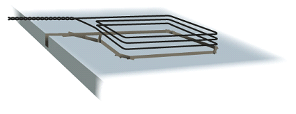
The sensitivity of most vehicle detectors is such that it takes an object the size of a 5 gallon steel paint bucket passing through the center of the loop to trigger the circuitry. As a rule, most vehicles will be detected if they drive alongside one of the edges of the loop. From an installation design standpoint, you should size the loop and position it so that at least one foot of the passing vehicle body is over the loop at any time. If loop is bigger than 5’ x 8’, opt for even more overlay. In general, center the loop in the traffic lane insuring no point of the loop is closer than 2 feet from any lane that is not being counted.
The inductive loop sensor embedded in the road is a type of radio antenna (RF Emitter). They operate at a very low power and a frequency that does not bother most other radio devices; however their function can be disrupted by strong CB radio transmissions, overhead power lines and nearby lightning strikes. The TT-14, TT-21, TT- 41 and Sprite counters have built in RF and EMP protection for the circuits for most cases, but these anomalies, while not damaging the unit, generally cause the traffic counter to count. This is generally not a significant problem except for overhead or underground AC power lines. We recommend installing counters 75 feet from 440 volt lines and 500 feet from large power lines.
Common loop sizes are:
- 6’x6’ (most common) or 5’x5’ with 3 to 4 wraps of wire
- 5’x8’, 5’x10’ and 5’x12’ with 3 wraps of wire
- All wires are generally 14 AWG (American Wire Gauge) multi-strands, with insulation jacket impervious to water, sunlight, gasoline, oil and mildew
Basic Site Selection Guidelines
If you are counting only one lane of a two lane road, verify that cars stay in their assigned lane and that they are ideally traveling faster than 10 Mph. If travel speeds are slower than 10 Mph, or in the event of a long vehicle, then you will likely need to be concerned with the setting of the time delay feature on the TT-21, TT-41 and Sprite.
If you are installing more than 1 loop in a road, do not install them directly opposite each other. Instead, stagger them about 10’ from edge to edge so as not to cause radio frequency (RF) interference between the loops (also known as crosstalk).
The Sprite battery life is typically 6 - 9 months using 1 loop, and 4 - 6 months operating 2 loops. The TT-14, TT-21, TT-41 series traffic counters are single inductive loop counters with a battery life of 12 - 18 months. When installing, if your home-run distance is greater than 50’, contact Diamond Traffic Products (support@diamondtraffic.com or 541-782-3903) for specific guidance.
The Pegasus, Unicorn and Phoenix counter/classifiers are capable of operating 4 to 16 loops. Battery life varies from 1 to 4 weeks depending upon the number of loops being used. The counters are capable of being located several hundred feet away from the loops. They can also tolerate slow vehicles and vehicles stopped over the loop for a short period of time (about 45 to 90 seconds).
 In order to locate one of these traffic counters more than 50’ from it’s loops, the factory will have to make circuit modifications for the counters to work at that distance. This modification will require a larger power draw, which will result in a slight reduction of battery life.
Directional Traffic
If you have a two lane road where vehicles travel in their assigned lanes, its best to install a separate inductive loop in each lane and obtain vehicle count data for each lane. You will need to connect each loop to its own traffic counter or classifier, or to a counter / classifier that has two or more loop detector channels.
Using a single loop, on a narrow road (or single lane of traffic) where vehicles may travel in either direction primarily near the center or crown of the roadway, counts are limited to a total of the combined data. Unless you install two or more loops and the appropriate traffic counter.
As an example, if you needed Directional Count on a 1 lane road you could install the Diamond Traffic Tally Sprite which has two inductive loops. You could install two loops in the road, spaced about 16 feet apart. When properly configured the Sprite can determine vehicle direction based upon which loop was crossed first.
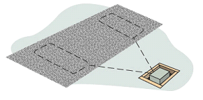
Install the traffic counter at the side of the road, but avoid drainage ditches and wet areas. Give thought as to how you are going to protect the traffic counter from flood waters, snow, vandalism and theft. Most agencies at permanent sites where there is no pedestrian traffic, locate counters in a recess in the ground that cannot be observed by passing vehicles.
Where possible excavate a 2' or 3' ft deep hole and fill it half or better full with coarse rocks for drainage and install a simple wood or metal wall on top of the rock to keep dirt and debris from sifting into the recessed well.
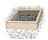
Cover the recessed well with boards or plywood to complete the installation. For increased concealment, located wells behind a tree or bush. If visibility is not of a concern, then one of our security boxes on a 3” diameter, 4’ long steel post could be installed. The security post is typically anchored in 2’ of concrete and extends 2’ above ground.
The aluminum security box is bolted to the top of the post. If you are in a location where pedestrians will likely spot the counter, or flooding is an issue; we recommend using this lockable water tight security box.
See our catalog or website (www.diamondtraffic.com) for security boxes and cabinets that we offer.
Paved Road Loops
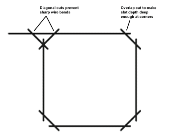
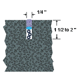
Paved road loops must be installed by cutting a square or rectangular slot in the roadway to receive the loop wire. A slot (see cross section below) typically measures 1/4 inch (4mm) in width and is cut to a depth of 1 1/2 to 2 inches (4 – 5 cm) deep.
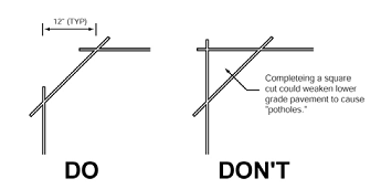
If the pavement thickness is very shallow, opt for the 1 1/2 inch deep slot. Because the 90 degree corners of these inductive loops have a sharp inside edge that will damage the loop wire insulation, you will need to cut a 45 degree slash cut across each corner. This cut should start about 12 inches (30 cm) back from the corner to prevent the small triangular piece of pavement in the center of the corner cuts from breaking out.
Once your saw cuts are made, clean out any mud and debris from inside, and around the slot cuts. If you elect to use water, garden hose water pressure is sufficien, but you'll then need to use compressed air to blow excess water and debris out of each slot. If air is not available, clean rags and paint stirring sticks can be used to dry the slot, as it must be clean and dry before wire installation.
To lay in loop wire, start at the point where the counter will be installed (usually some distance from the roadway where a station, well or s. Run the wire to and through the lead-in slot to the corner of the loop. Continue to lay the wire around the loop slots; clock-wise or counter-clockwise will not matter as long as you are consistent through the loop. Lay in three or four passes around the loop saw cut. Lay the loop wire back through the lead-in slot back to the traffic counter.

The portion of the wire that is outside the pavement transitioning over to the traffic counter should be twisted four to six times per foot. We recommend that you slip this twisted lead-in wire inside plastic PVC pipe (1/2 or 3/4 inch) in order to better protect it from sharp objects in the ground.
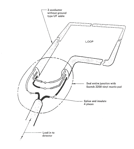
Connect the two loop wires to the two green wires of the TT-21 / TT-41 pigtail (the red and black wires of the pigtail are for tripping an external device). Tape the red and black wires off so they don’t short out to anything, including themselves. Solder and seal the joints between loop wire and green wire.
 NOTE: Failure to properly solder these will eventually cause counting problems due to oxidation.
Seal the open slot in the roadway with the appropriate sealant for the pavement type; crack sealant, epoxy loop sealant, or a variety of other sealants. Our recommendation is Pro Seal 6006 Loop Sealant. DO NOT USE HOT TAR, and hard setting epoxies should never be used with asphalt.
Dirt and Gravel Inductive Loops
The 14 gauge wire used in paved road installation does not have a sufficient insulation jacket to withstand the sharp rocks and gravel. Therefore, inductive loops in unpaved roads are constructed using 14 gauge, 3 or 4 conductor direct buried UF cable. This is readily available at most local hardware or building supply stores. We also stock it here at Diamond Traffic Products as a service to our customers.

To install an inductive loop in an unpaved road, you generally must install a loop that covers the roadway from side to side, to within four feet of each edge. Without lane assignment markings, drivers on dirt and gravel roads typically will drive on the right, left and/or in the middle of these roads. If you need directional counts, consider installing two loops as diagrammed in the ‘Directional Traffic’ section.
For example, whether you’re collecting ‘Combined Count’ or ‘Directional’ data; if your road is 25 feet wide, your loop should measure 5’ x 17’
Having decided upon the loop size, cut two lengths as follows: Add together the lengths of the four loop sides, the length of the lead-in (home run) and 5 – 6 additional feet as spare.
Splice the wires as shown in Diagram 2 – Loop Installation. Stagger your joints as the finished insulated joint will be thick and bulky. SOLDER YOUR JOINTS. You can use the 3m Scotch 2200 vinyl splice kit, but it is big, rigid and expensive. Two layers of shrink tube, wrapped with several loops of electrical tape, then covered with roofing tar works very well.
The loop wire in paved roads is only 1 1/2 to 2 inches below the road surface. For gravel roads, you need to consider how deep the road grader reworks the road. If the grader uses the blade only, then ten inches below the surface is sufficient. If they typically drop their rip teeth and re-level the road, we advise that you install at a depth of 18 inches.
While it is not absolutely necessary to back fill over the loop wire with sand or soft soil, we recommend doing so to prevent potential damage caused by sharp rocks lying against the UF cable.
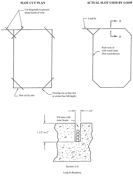
Diagram 1 – Slot Cuts
Diagram 2 – Loop Installation
ALLOWED INDUCTIVE LOOP ANTENNAS
The 4 Channel inductive loop detector version #2.10 was designed to operate in the FCC allowed RF Frequency for sizes and inductive values listed in chart below.
Size, shape, number of turns and induction are critical to keep in the operating frequency within the FCC allowed limits. Loop sizes and turns shown in the yellow area of the card will cause the detector to operate outside of the FCC legal frequency. Also, due to their small size and few turns loops in the yellow area detect vehicles poorly.
Best practices call for a minimum of at least (3) turns. If loop antenna is any other size then those listed below. Contact Diamond Traffic Products for assistance.
** Number indicates micro-henries. **
|
Length (Feet)
|
Width (Feet)
|
1 Turn
|
2 Turns
|
3 Turns
|
4 Turns
|
5 Turns
|
|
2
|
4
|
5
|
16
|
33
|
55
|
81
|
|
2
|
6
|
6
|
22
|
45
|
75
|
112
|
|
2
|
8
|
8
|
28
|
57
|
95
|
142
|
|
4
|
4
|
7
|
23
|
47
|
79
|
118
|
|
4
|
6
|
9
|
29
|
61
|
103
|
153
|
|
4
|
8
|
10
|
36
|
75
|
126
|
188
|
|
4
|
10
|
12
|
43
|
89
|
149
|
223
|
|
4
|
12
|
14
|
49
|
102
|
172
|
257
|
|
4
|
14
|
16
|
56
|
116
|
195
|
292
|
|
4
|
16
|
18
|
62
|
129
|
218
|
326
|
|
5
|
5
|
9
|
30
|
72
|
104
|
155
|
|
5
|
8
|
11
|
40
|
83
|
140
|
209
|
|
5
|
10
|
13
|
52
|
97
|
164
|
245
|
|
6
|
6
|
11
|
37
|
76
|
129
|
192
|
|
6
|
8
|
13
|
44
|
91
|
154
|
230
|
|
6
|
10
|
14
|
51
|
106
|
178
|
267
|
|
6
|
12
|
16
|
58
|
120
|
203
|
305
|
|
6
|
14
|
18
|
65
|
135
|
228
|
342
|
|
6
|
16
|
20
|
71
|
149
|
252
|
379
|
|
6
|
18
|
22
|
78
|
164
|
277
|
416
|
|
6
|
20
|
24
|
85
|
178
|
301
|
452
|
|
6
|
22
|
26
|
92
|
193
|
326
|
489
|
|
6
|
24
|
28
|
99
|
207
|
350
|
526
|
|
8
|
8
|
15
|
51
|
107
|
180
|
270
|
Antenna Information
Users (government agencies) install the inductive loop sensor antennas in the road surface. The typical traffic counting loop will use 14 to 18 AW gauge; 8-80 strand wire in loops ranging from 4 ft X 4 ft to 8 ft X 8 ft, with lead-in wire ranging from 25 ft to 600 ft long. The effective inductance is kept within a defined range as detailed in the Road Loop Installation Guide.
Loop inductance must be between 65 to 500uH. Oscillation frequency will range from 88 kHz for 65 kHz to 29 kHz for 500uH. Transmitted power is effectively the same throughout this range. During installation, the loop antennas are permanently soldered to the loop detector by professional installers according to the loop installation guide.


 The article has been updated successfully.


