Overview
Below we discuss the various ways the Phoenix MDK can collect data, and what types of sensors are required to collect each type of data. Please read this section carefully. The Phoenix MDK is a very sophisticated counter/classifier with many options. Reading and understanding this section first will greatly simplify operation later.
Sensor Miss Code Definitions:
|
SnMis #0 -
|
Occurs only with Axle-Pres-Axle or Pres-Axle-Pres combinations. This error indicated an improper sequence of sensor activations or missing one or more activation(s).
|
|
SnMis #1 -
|
The counter only got a road tube #1 strike, with no further road tube activations. This can happen if a vehicle hits the first road tube, but misses the second while changing lanes.
|
|
SnMis #2 -
|
The counter only received a road tube #2 strike, without first getting a road tube 1 strike. This, like SnMis #1, can happen if a vehicle crosses into the lane but misses’ road tube #1.
|
|
SnMis #3 -
|
Is an over speed or under speed vehicle, and can optionally be used to indicate vehicles which only hit road tube #1 and road tube #2 once, with no further activations. Note that the counter will normally turn these types of activations into two axle vehicles with the axle length equal to the sensor spacing.
|
The Four Basic Storage Modes
Before attempting to use your Phoenix MDK, you should first become familiar with the four fundamental modes of operation. The mode that you select determines the type of data that will be collected, and whether the information will be combined with other entries or stored individually. These modes do not cover WIM applications.
|
Timestamp/Sensor
|
-
|
Sensor mode stores individual sensor pulses into memory with an accurate timestamp. This mode bypasses the Phoenix MDK regular data analysis routines and allows users to get an exact copy of what the counter saw on the roadway. Software, such as Centurion can then be used to analyze this data into other forms as the user requires.
|
|
Per-Vehicle/Raw
|
-
|
This mode will store each individual vehicle in memory as it passes by. The following information about each vehicle can be stored in memory: time, speed, number of axles, spacing between each axle, overall length, bin classification and axle weights if Phoenix MDK is equipped with the WIM option.
|
|
Binned
|
-
|
This mode is the conventional classifier storage mode. Each vehicle is analyzed and classified into the appropriate bin number for each of the following five classes: Axle Class, Speed Class, Length Class, Gap Class, & Headway Class. The parameters for determining what types of vehicles belong to each bin number can be changed by the user, with the most commonly used values being built into the Phoenix MDK. Users specify a time interval, such as every 15 minutes, in which the total number of vehicles for each bin will be stored in memory.
|
|
Count
|
-
|
The count mode is one of the simplest modes of operation. It is used when just a vehicle count is desired. When using Road Tubes or Piezo Sensors; the Phoenix MDK provides the total number of axles detected, optionally divided by two. When using Inductive Loops, the Phoenix MDK will give the number of vehicles. Users specify a time interval, such as every hour, in which these total counts will be stored in memory.
|
Sensor and Sensor Modes
The Phoenix MDK supports Road Tube Air Switches, Inductive Loops, Remote Inputs, Piezo Resistive and Piezo Electric Inputs. Road Tubes, Remote Inputs, and Piezo Sensors are considered “axle” sensors, since they are activated by individual axles. Inductive Loops are considered “presence” sensors, since they become activated by the metal in the vehicle passing over, and become un-active when the vehicle leaves. The Remote input will support any type of sensor which will give a momentary switch closure.
Since there are variations with each sensor (for example, Inductive Loops will have slightly different amounts of inductance), the Phoenix MDK performs automatic tuning or adjustment for all sensors except for Piezo Resistive by default. The user must tune Piezos manually or enable auto piezo calibration during setup using the Phoenix MDK keypad or a PC/laptop computer and the Centurion Software. See section 3d3 for more information.
When in Per-Vehicle (raw) storage or Binned storage modes, four types of sensor arrangements (sensor modes) may be selected:
|
Axle-Axle
|
-
|
Two axle sensors, such as two tubes.
|
|
Pres-Pres
|
-
|
Two presence sensors, such as two loops.
|
|
Axle-Pres-Axle
|
-
|
Two Axle sensors and one presence sensor.
|
|
Pres-Axle-Pres
|
-
|
Two presence sensors and one axle sensor.
|
In Count Storage mode, you can select either a Presence Sensor or an Axle Sensor. In Timestamp (Sensor) Storage mode, you can select a Presence Sensor, an Axle Sensor, or Both.
The way sensors are divided up among the lanes depends on the storage mode (Raw, Binned, etc.) and the sensor mode (Axle-Axle, Pres-Pres, etc.). Table 1 shows the divisions of the sensors.
|
|
Table 1
|
|
|
Count & Sensor Storage
|
Raw & Binned Storage
|
|
Lane Number
|
Axle (Tubes)
|
Pres (Loops)
|
Axle (Tubes)
|
Pres (Loops)
|
|
#1
|
1
|
1
|
1 & 2
|
1 & 2
|
|
#2
|
2
|
2
|
3 & 4
|
3 & 4
|
|
#3
|
3
|
3
|
5 & 6
|
5 & 6
|
|
#4
|
4
|
4
|
7 & 8
|
7 & 8
|
|
#5
|
5
|
5
|
n/a
|
9 & 10
|
|
#6
|
6
|
6
|
11 & 12
|
|
#7
|
7
|
7
|
13 & 14
|
|
#8
|
8
|
8
|
15 & 16
|
|
#9
|
n/a
|
9
|
2 & 1 (directional)
|
2 & 1 (directional)
|
|
#10
|
10
|
4 & 3 (directional)
|
4 & 3 (directional)
|
|
#11
|
11
|
5 & 6 (directional)
|
5 & 6 (directional)
|
|
#12
|
12
|
7 & 8 (directional)
|
7 & 8 (directional)
|
|
#13
|
13
|
n/a
|
10 & 9 (directional)
|
|
#14
|
14
|
12 & 11 (directional)
|
|
#15
|
15
|
14 & 13 (directional)
|
|
#16
|
16
|
15 & 16 (directional)
|
Sensor and Count Modes always use the same lane number as the sensor number for input to that lane. Per-Vehicle (Raw) and Binned Modes will always use two inputs for each lane, with the sensor numbers shown in the table.
Per-Vehicle (Raw) and Binned modes are the classification modes, so they can also take advantage of two slightly more complicated sensor modes, “Axle-Pres-Axle” and “Pres-Axle-Pres”. The first and last sensors, either the two Axle or the two Pres, are ALWAYS the same as shown in Table 1. The difference comes in the middle sensor.
|
Table 2 – Configuration of Three Sensor Lanes
|
|
Mode
|
Lane 1
|
Lane 2
|
Lane 3
|
Lane 4
|
Lane 5
|
Lane 6
|
Lane 7
|
Lane 8
|
|
Axle
|
1
|
3
|
5
|
7
|
n/a
|
|
Pres
|
2
|
2
|
3
|
4
|
|
Axle
|
2
|
4
|
6
|
8
|
|
Pres
|
1
|
3
|
5
|
7
|
9
|
11
|
13
|
15
|
|
Axle
|
1
|
2
|
3
|
4
|
5
|
6
|
7
|
8
|
|
Pres
|
2
|
4
|
6
|
8
|
10
|
12
|
14
|
16
|
Sensor Conflicts:
The system works AS LONG AS THERE IS NEVER ANY CONFLICT BETWEEN LANES FOR SENSORS. This can occur if you use different axle configurations on different lanes and you are using “Axle-Pres-Axle” or “Pres-Axle-Pres” on the higher numbered lane. Still confusing? Hang in there, it gets simpler. Let’s try an example.
Example 1: Suppose you selected Pres-Pres for lane #1 and Axle-Pres-Axle for lane #2, according to the Table 1 (for lane #1) and Table 2 (for lane #2).
|
Table 3 – Example 1
|
|
Mode
|
Lane 1
|
Lane 2
|
|
Pres-Pres
|
Pres1, Pres 2
|
-------------------
|
|
Axle-Pres-Axle
|
-------------------
|
Axle 3, Pres 2, Axle 4
|
In this case, Pres 2 (underlined) is specified for BOTH lanes 1 and 2! This situation is referred to as a SENSOR CONFLICT and is automatically detected by the software. If a conflict occurs, the Phoenix MDK will not allow you to start collecting until the conflict is resolved.
Now, for further example, suppose you chose Axle-Pres-Axle for lane #1 and Pres-Pres for lane #2, according to the same tables.
|
Table 4 – Example 2
|
|
Mode
|
Lane 1
|
Lane 2
|
|
Axle-Pres-Axle
|
Axle 1,Pres 1, Axle 2
|
-------------------
|
|
Pres-Pres
|
-------------------
|
Pres 3, Pres 4
|
Now, there is no conflict and the system can operate. When the system does detect a sensor conflict with another lane (and note that the higher number lane will always be the lane in conflict, so lane #1 will never be in conflict since it is the lowest lane number), you will receive an error message and the software will not continue operation.
The Phoenix MDK also contains many advanced sensor analysis routines to improve data accuracy, including examining both sets of axle and presence sensors, the tossing out of too short spacing (for example: eliminating a road tube bounce, which can cause a false count), and the determination of missed axles.
Dynamic Sensor Assigning:
Since the Phoenix MDK uses sensors in a certain order (depending on setup) sometimes your configuration is limited by the default assignment of sensors. To accommodate unconventional sensor inputs, the Phoenix MDK allows for the sensors to be rearranged or reassigned to different inputs. This feature is only available during serial port programming via the PC. The assignment of sensors is done by lane and is done using the Centurion software. Sensors can be assigned to any lane in any combination with the exception that the sensor not be assigned more than once.
As an example you may have a site that was wired incorrectly and cannot be rewired easily. In this case it may be easier to just reassign the sensor inputs to allow the unit to count or classify traffic correctly. In the following table the scenario represented would be that of a site that was “wired” backwards. By reassigning the sensor inputs we have allowed the lane assignments to appear correctly:
|
Before Reassignment
|
fter Reassignment
|
|
Sensor
|
Lane
|
Sensor
|
Lane
|
|
Axle 1
|
5
|
Axle 1
|
1
|
|
Axle 2
|
6
|
Axle 2
|
2
|
|
Axle 3
|
7
|
Axle 3
|
3
|
|
Axle 4
|
8
|
Axle 4
|
4
|
|
Axle 5
|
1
|
Axle 5
|
5
|
|
Axle 6
|
2
|
Axle 6
|
6
|
|
Axle 7
|
3
|
Axle 7
|
7
|
|
Axle 8
|
4
|
Axle 8
|
8
|
Per-Vehicle (Raw) Storage and Specific Functions:
In this mode, an individual record is kept for each vehicle encountered. Any combination of one to eight lanes (depending on how many and what type of sensor inputs the boards are installed) can be enabled. If any lane is configured for directional mode (the ability to classify traffic traveling in either direction), an additional lane of traffic data is created. For example, if lane # 1 is enabled and is configured in directional mode, the counter would create lane # 9 for vehicles traveling in the opposite direction on lane # 1.
|
Physical Lane
|
Opposite Lane Direction
|
|
Lane #1
|
Lane #9
|
|
Lane #2
|
Lane #10
|
|
Lane #3
|
Lane #11
|
|
Lane #4
|
Lane #12
|
|
Lane #5
|
Lane #13
|
|
Lane #6
|
Lane #14
|
|
Lane #7
|
Lane #15
|
|
Lane #8
|
Lane #16
|
Note that the directional lane is not an actual separate lane – it is the same physical lane but simply traffic moving in the opposite direction. It is recommended that the directional option be used whenever the possibility of two-way traffic exists, such as a one-lane road or an area on a two lane highway where there is much passing of slower vehicles, thereby using the oncoming lane.
Four separate modes of Per-Vehicle (Raw) Storage are available. Lanes are not individually set; all lanes will be in the same mode.
|
Normal
|
-
|
This is a straight raw vehicle mode which will store lane number, time, speed, number of axles, and spacing between each axle.
|
|
Enhanced
|
-
|
This data is in the same format as Normal with the exception that speed is now calculated to tenths of a MPH (or KPH) and the overall vehicle length axle is added to the record.
|
|
Raw with Bins
|
-
|
The data is the same as Normal except the Speed, Axles, Length, Gap, and Headway bin numbers are stored with each record based on the current bin tables in the unit. This format does not store the data in binned format, but will tell you what bin a vehicle would have gone into if you were binning.
|
|
Enhanced with Bins
|
-
|
This format is a combination (as the name implies) of Enhanced and Raw with Bins. The data is now Enhanced and stored with the bin numbers.
|
There is some give and take with the modes. Enhanced Raw will give a more precise record than Normal Raw; however, more memory space is used. The same comment goes for Raw with Bins – more memory to keep track of which bin it would have gone into. Appendix B gives an approximation of the number of vehicles which can be stored in memory depending upon which mode you choose.
While in Raw Storage, the user can select any of the four Sensor Modes (Axle-Axle, Pres-Pres, etc.) for each lane. The system will ask the user for Sensor Spacing and the Loop Length (if using presence). The maximum sensor spacing is 99.9 feet, and the maximum loop length is 25.5 feet.
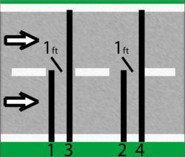
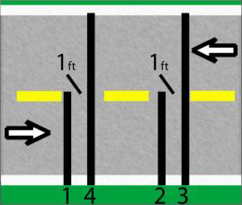
Per-Vehicle (Raw) Storage also supports “Lane Overlap”. If axle sensors are used to collect data from two lanes of traffic, the Lanes can be configured as shown in the figures below. Note that the shorter tube is in the near lane (lane #1), and is activated first by oncoming traffic. This configuration will allow you to collect data from two lanes using four road tubes where one set of tubes crosses both lanes.
 |
|
 |
| Same Direction |
|
Opposite Direction |
As shown, lane overlap can support lanes where vehicles are going the same or opposite direction.
Per-Vehicle (Raw) data is stored in a straight fashion. As vehicles are detected and the information (speed, length, etc.) is gathered, the data is stored sequentially in memory in long record. During collection, or during testing, the Phoenix MDK will allow you to monitor any or all lanes.
Binned Storage and Specification Functions
Binned Storage is very similar to Per-Vehicle (Raw) storage that you can have any combination of lanes and each lane can be enabled for directional operation shown as additional lanes of traffic. Binned Storage supports the same sensor modes and lane configurations.
The difference in the modes is the method of storage. In Per-Vehicle (Raw) Storage, the Phoenix MDK stores all data in chronological order as the vehicles are detected and data is registered (speed, length, etc.). Binned Storage sorts and classifies the data into separate categories or “Bins”. The vehicle is then added to the correct Bin #. In this fashion, you can retrieve totals for various types of vehicles.
There are five classification Bin types (not Including WIM data):
|
Axle
|
-
|
Data is binned by number of Axles and Spacing Classification. For example: Scheme-F, which has 13 bins, 30 bins are available if needed.
|
|
Speed
|
-
|
Data is binned by the individual vehicles speed. 30 speed bins are available.
|
|
Length
|
-
|
Data is binned by the individual vehicles overall length. 30 length bins are available.
|
|
Gap
|
-
|
Data is binned by the distance between vehicles, from the tail of the first vehicle to the nose of the second vehicle (up to 30 bins).
|
|
Headway
|
-
|
Data is binned by the time vehicles are going in the same direction, from the nose of the first vehicle to the nose of the second vehicle (up to 30 bins).
|
Each lane can also be enabled to do two dimensional binning of either “Speed by Length”, “Speed by Axle”, or both. This mode creates a table giving you individual speed bins for each vehicle type or for each vehicle length category.
Each category or “Bin” has been predefined as to what it represents. For example, Axle Bin #1 is for motorcycles, Speed Bin #1 is for vehicles traveling between 1 and 19.9 MPH. While these bins have preset to be the most common categories, you may change the type and number of bins for each binning mode. See the Centurion Software Help Menu for more information on modifying these bin definitions to your own specific needs.
Binning Storage also supports the “Lane Overlap” function. Refer to the previous section, “Per-Vehicle (Raw) Storage and Specific Functions” for a detailed explanation.
Count Storage and Specific Functions
In Count Storage Mode, the only information stored is the number of vehicles that have been detected in each lane. Up to 16 lanes are supported (depending on the number and type of sensors input boards installed) in this mode. Normally, each lane will use one sensor to collect the count. When a Road Tube or Piezo Sensor is used as the lane sensor, the count may be divided by two. Since loop sensors hold presence for the duration of a vehicle, the divide by two option is not used by loops.
Storage of the counts is performed in the same manner as outlined above for Binned data (i.e. using “record intervals”).
There are two specialized sensor configurations for count data when two axle sensors are used (normally road tubes); they are Lane Subtraction and Directional.
|
Lane Subtraction
|
-
|
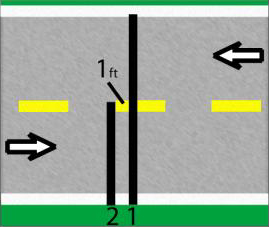
This mode is used when you want to get individual lane count from two different lanes of traffic from one side of the road. The road tube attached to lane 1 (or any other ODD numbered lane) is laid out across both lanes. The road tube attached to Lane 2 (or the next even numbered lane) is laid out across one lane. The Phoenix MDK will subtract the even lanes from the odd lane’s count to obtain the proper directional count for the odd numbered lane.
 |
Traffic Direction does not matter
|
|
Odd Number Lane Must Be Longer Tube (i.e. Lanes 1,3,5,7,9,11,13, or15)
|
|
|
Directional
|
-
|
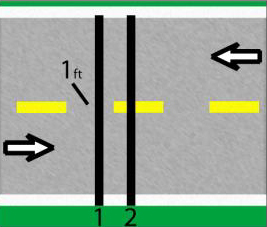
This mode is used for counting two-way traffic on a narrow road. A road tube pair (such as 1-2 or 3-4) are laid out across both lanes with road tube one foot apart. The phoenix will determine (from the order of actuation) the proper directional count for each lane.
|
You can monitor any or all lanes during collection or testing, with the system showing you the current lane totals for the record interval.
Sensor Storage and Specific Functions
Sensor Data Storage or (Timestamp) is a flexible mode of storing traffic data. Data is stored sequentially when a sensor is activated, allowing custom software to organize the data in a way tailor made for the user.
Sensor Data Storage (Timestamp) stores the simplest form of data. Inside the Phoenix MDK is a timer that counts down (starting from 16,777,216) at the rate of 10.695 KHz (10,695 cycles per second). When its 24-bit timer counts down to zero, it recycles to 16,777,215. At the rate of 10.695 KHz, the time it takes to revolve through the counter is 16777215/10695 or about 26 minutes. When a sensor is activated, the counter stores the lane, type of sensor, and the timer reading. When the sensor is activated again, it stores the lane, time, type of sensor, and the new timer reading. The counter will store an “A On” for an axle strike, a “P On” for a presence sensor turning on, or a “P Off” for a presence sensor turning off.
Example:
Let’s say we have two Presence sensors in a road, 10 feet from the leading edge. In the Phoenix MDK, we turn on Lane #1 and Lane #2 and select Pres as the sensor.
A record of strikes might appear as such –
1:14:38:56 (3369138) P On
2:14:38:56 (3367017) P On
1:14:38:56 (3366577) P Off
2:14:38:56 (3364057) P Off
Now, what this means is that the Presence Sensor in Lane 1 was activated at 14:38:56 (2:38pm + 56 seconds) when the timer was at 3,369,138. Lane 2 was activated with a Presence On when the timer was at 3,367,017. Lane 1 lost presence of a vehicle when the timer was at 3,366,577. Lane 2 lost presence of a vehicle when the timer was at 3,364,057.
The question you might ask now is, “OK, so what’s the point?” Well, we know
- The distance (10 Feet)
- The time from activating the first sensor to activating the second sensor, this is a 3,369,138-3,367,017 = 2,121 timer cycle.
Since we know the timer is running at 10,695 cycles per second, we can divide the number of cycles by the cycles per second rate and get the amount of time, or 2,121/10,695 = .198317 seconds. Now, since distance = rate X time, then rate = distance/time, or 10 feet/.198317 seconds = @50.42 feet per second. Using some conversions, this comes out to about 34.4 Mph. (if it’s a 25 Mph zone, somebody is speeding!).
Since you know the loop length, and have calculated the vehicle speed, you could also calculate the length of the vehicle. This is the exact process the Phoenix MDK used in Binned and Per-Vehicle (Raw) Modes.
If you were using tubes, you could calculate speed, number of axles, axle length between individual axles, and overall axle length. Combine the two (using the option of Axle-Pres-Axle or Pres-Axle-Pres) and you can calculate everything the tubes can plus overall vehicle length. Quite a bit of information from a few timer counts.
As with other storage modes, during testing or collection you can monitor any or all lanes.


 The article has been updated successfully.


