Overview
Inductive loops consist of one or more turns of wire, usually arranged in a rectangle. Inductive loops, as their name implies, operate by exploiting the electrical property of inductance. Inductance, measured in microhenries, can be defined as that property of an electric circuit whereby electromotive force is induced in a circuit by a change of current.

But how is this property applied to traffic detection
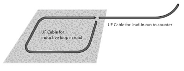
The loop is buried just below the surface of the roadway and connected to the terminals of the traffic counter by a pair of wires, called a lead-in. The traffic detector drives an alternating flow of current through the loop at or below resonating frequency (operating frequencies range from 20,000 to 120,000 cycles per second – or 20 to 120 kilohertz (KHz). When a vehicle crosses the loop, eddy currents are induced causing an apparent drop in loop inductance. The detector senses this change and advances a recording mechanism to register a count.

Loop Detectors monitor inductance in several ways
With Self-tuning detectors, the oscillator is automatically adjusted to a null condition in feedback circuits. Any drop in inductance temporarily “de-tunes” the loop, causing a phase shift or amplitude change in the current flowing through the loop. Long-term inductance changes, such as a vehicle parked on part of the loop, are compensated for by the feedback circuit automatically tuning to a new null.
Manually tuned detectors, a tuned condition is achieved by adjusting the capacitance of the output circuit to match the loop detectors fixed frequency. No compensation is provided for long term inductance changes.
A third type of detector uses a balanced bridge circuit. The loop is placed on one arm of the bridge. A vehicle caused drop in inductance unbalanced the bridge causing an output signal. The most critical problem is maintaining balance despite changes in lead in capacitance, which varies with temperature and moisture. This is also a problem with manually tuned detectors. The balanced bridge detector does not compensate for long term inductance changes.
Besides inductance and capacitance
Loops and lead-ins exhibit the electrical property of resistance and the frequency related properties of reactance, impedance, resonance and “Q,” the quality factor of the loop. Traffic detectors respond to the net effect of these properties or to changes in them. Studies indicate that when designing a loop, it is sufficient to consider only effective inductance; that is, the inductance presented to the terminals of the detector.
Effective inductance includes not only the inductance of the loop, but also the effects of inductance and capacitance of the lead in. Most detectors operate with inductances ranging from 50 to 500 microhenries. But based on real world application, effective inductance of the loop installation should be between 100 and 300 microhenries for more accurate vehicle traffic counting.
To achieve this both the choice of wire is important, as well as the physical design of the loop itself.